
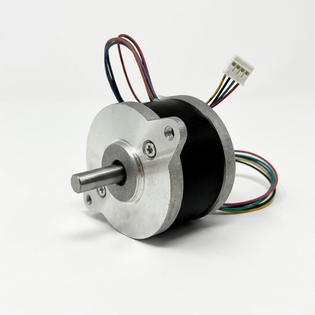
Stepper Motor Winding Guide: Bipolar Series vs. Parallel, Unipolar, and Inductance Sizing for OEMs
Compare stepper motor winding options, series vs parallel current, and inductance limits. Use worked examples and an OEM checklist to prepare your winding RFQ.
Selection summary
- Bipolar series vs. parallel: For an 8-lead motor with matched, magnetically coupled half-windings, series has approximately four times the phase inductance and four times the resistance of parallel. At equal copper loss, parallel requires twice the driver phase current. Confirm the connection-specific motor ratings before changing settings.
- 4, 6, or 8 leads: A 4-lead motor has a fixed bipolar connection. A 6-lead motor supports full-winding or half-coil bipolar operation; external parallel wiring requires eight independent leads.
- Select at operating speed: Holding torque describes standstill performance. Use a torque-speed curve measured with the proposed driver, winding connection, bus voltage, current convention, and load profile.
- Inductance sizing: Lower inductance and higher permitted bus voltage can improve current tracking at speed. Neither inductance alone nor a voltage rule of thumb establishes a universal RPM limit.
- Procurement output: Freeze the connection, phase resistance and inductance measurement conditions, rated current, pinout, thermal limits, and sample acceptance criteria in the RFQ.
Scope and review date: Reviewed 2 November 2026 for global OEM buyers and application engineers using two-phase hybrid NEMA stepper motors with current-regulated drives. Equations below are screening models for matched windings; saturation, driver decay behavior, back-EMF, cooling, and load inertia require application validation. Worked values and curves are illustrative, with no measured motor-test results claimed. This guide does not establish electrical safety certification or a production test specification.
Preparing a winding specification? Discuss the connection, driver, and motion profile with our engineering team.
In motion control engineering, selecting a NEMA stepper motor requires more than frame size and holding torque. Phase resistance, phase inductance, back-EMF, driver behavior, and the mechanical load together determine whether the axis can meet its cycle time without losing steps.
If a prototype holds position but loses torque during acceleration, compare winding and driver limits alongside resonance, friction, load inertia, and acceleration settings before increasing the motor frame size. The guide below turns that investigation into a connection comparison and a procurement checklist.
1. First Principles: Resistance, Inductance, and Current Rise Time
A common 1.8° two-phase hybrid stepper uses a 50-tooth permanent-magnet rotor and a wound stator; other step angles and constructions differ. Electrically, each stator phase can be modeled as a series resistor-inductor (R-L) circuit with an opposing voltage generator representing back-EMF (E_b):
V_phase(t) = i(t) R + L (di(t))/(dt) + E_b(omega_m)Where:
V_phase(t)is the instantaneous voltage applied across the phase winding [V].i(t)is the instantaneous winding current [A].Ris the total DC phase resistance [Ω].Lis the total phase inductance [HormH].E_b(omega_m) = K_e × omega_mis the back-EMF proportional to rotor angular velocityomega_m[rad/s] and back-EMF constantK_e[V×s/rad].
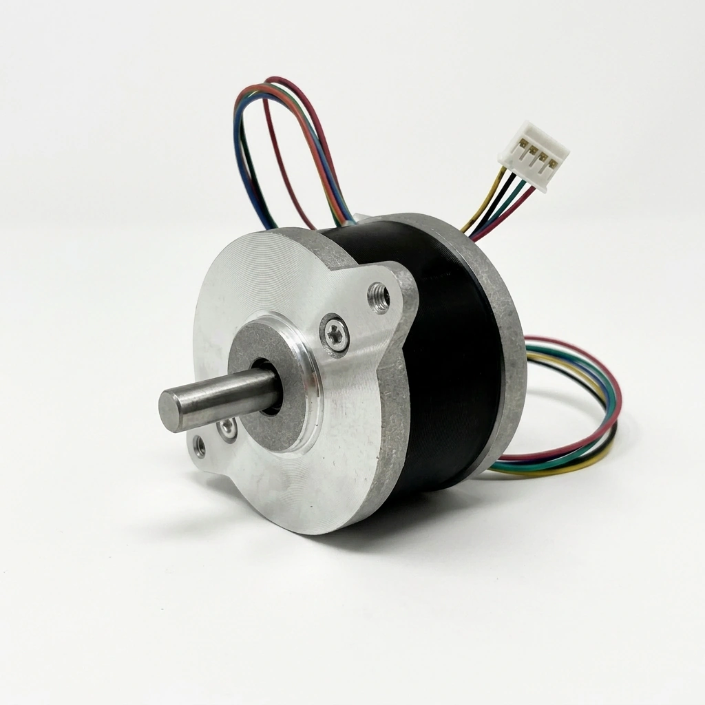
The Electrical Time Constant (tau) and Current Rise Rate
When a digital constant-current chopper driver (such as a DM542 or DM860) switches voltage onto a phase winding, the current cannot change instantaneously due to the magnetic energy stored in the inductor:
(di/dt) at i=0 = (V_bus - E_b)/(L)The natural electrical time constant tau of the winding is defined as:
tau = (L)/(R) [seconds]In an un-chopped R-L circuit, the current requires approximately 3tau to reach 95% of its asymptotic value (I_max = V/R). In a pulse-width modulation (PWM) chopper drive, with switching frequency set by its design, the drive applies the full DC bus voltage (V_bus) to force current into the coil as fast as possible. Once the current reaches the target setpoint (I_target), the drive chops the voltage to maintain that current level.
Why Inductance Chokes High-Speed Torque
At low step rates, the duration of each step pulse (t_step = 1 / f_step) is much longer than the electrical rise time t_rise ≈ (L × I_target)/(V_bus - E_b). The current can approach its commanded value; the available running torque must still be taken from the torque-speed curve.
However, as shaft speed increases, two limiting factors converge:
- Shrinking Step Period: At 1,200 RPM (4,000 full steps/sec for a 1.8° motor), each full step pulse lasts only
250 µs. If the winding inductance is high, the current rise time exceeds the step period. Current tracking can deteriorate and available torque can fall. External microstep pulse periods are not themselves the electrical current-reversal period. - Rising Back-EMF: The rotating permanent magnet rotor induces a sinusoidal voltage (
E_b) across the stator coils that directly opposes the driver's bus voltage. The effective voltage available to push current through the winding becomes(V_bus - E_b). As back-EMF approaches the bus voltage, the drive loses current-control headroom and stall risk rises under load.
Within the unsaturated operating region, ampere-turns influence available torque, so maintaining the intended phase-current waveform matters. Texas Instruments explains current regulation and decay modes in the DRV8825 datasheet, sections 8.3.2–8.3.3. Its component limits apply to that IC, not to DM-series modules.
2. Lead Configurations: 4-Lead, 6-Lead, and 8-Lead Topologies
Hybrid stepper motors are manufactured in three standard wire lead configurations. Understanding their internal architecture allows engineers to select the exact winding connection required for their machine's duty cycle.
Winding Architecture Schematics
Architectural Breakdown
-
4-Lead Motors (Fixed Bipolar):
- Internal Construction: The two coils per phase are interconnected internally at the factory in either series or parallel. Only four lead wires (A+, A-, B+, B-) exit the motor housing.
- Advantages: Lowest bill-of-materials (BOM) wiring cost, fewer field splices and opportunities for connection errors, smaller cable bundle diameter, and simple 4-pin industrial connectors (e.g. M12 or Deutsch).
- Limitations: Completely inflexible in the field. The customer cannot switch between low-current series and high-speed parallel operation.
-
6-Lead Motors (Center-Tapped):
- Internal Construction: Each phase winding has a center tap, yielding three leads per phase (End 1, Center Tap, End 2).
- Operation Modes:
- Unipolar Mode: Center tap connected to positive DC supply (
V+), while outer ends are switched to ground through driver MOSFETs. Only half the coil carries current at any instant. - Bipolar Series (Full Winding) Mode: Connect the two outer ends to a standard bipolar driver (A+, A-), leaving the center tap unconnected and insulated. This uses the full winding; an ideal equal-copper-loss comparison gives about 1.414 times the unipolar holding torque, subject to the motor ratings and magnetic saturation.
- Bipolar Half-Coil Mode: Connect the center tap and one outer lead to a bipolar driver, leaving the other outer lead insulated. This cuts inductance by 75% compared to full winding, achieving higher speed at the cost of lower holding torque.
- Unipolar Mode: Center tap connected to positive DC supply (
-
8-Lead Motors (Universal Configurable):
- Internal Construction: All four individual phase coils (two coils per stator phase) are brought out independently, providing eight separate lead wires.
- Operation Modes:
- Bipolar Series: Coil 1 and Coil 2 connected end-to-end. Delivers maximum torque per ampere at low RPM.
- Bipolar Parallel: Coil 1 and Coil 2 connected in parallel. Cuts phase inductance by a factor of 4 relative to series, providing superior high-speed torque.
- Unipolar: Coils interconnected to form center taps for legacy unipolar drives.
- OEM Procurement Recommendation: Ideal for prototyping platforms, machinery built for multi-voltage global export (e.g. 24V domestic vs. 70V export), or multi-axis machines with different torque-speed requirements. Export destination alone does not determine the required bus voltage.
3. Engineering Comparison Matrix: Winding Configurations
The matrix compares matched winding sections in the same motor design. R_uni, L_uni, and I_uni refer to one half-winding in the unipolar rating; torque ratios are approximate equal-copper-loss comparisons, not ratings for every 4-lead motor. Four leads alone do not identify an internal series or parallel arrangement. See Oriental Motor’s connection comparison.
| Parameter | 4-Lead Bipolar (Series) | 4-Lead Bipolar (Parallel) | 6-Lead Unipolar | 6-Lead Bipolar (Full Coil) | 8-Lead Bipolar Series | 8-Lead Bipolar Parallel |
|---|---|---|---|---|---|---|
| Number of External Leads | 4 wires | 4 wires | 6 wires | 6 wires (2 floating) | 8 wires | 8 wires |
| Active Stator Copper Volume | 100% | 100% | 50% per phase half | 100% | 100% | 100% |
Normalized Phase Resistance (R) | 2.0 × R_uni | 0.5 × R_uni | 1.0 × R_uni | 2.0 × R_uni | 2.0 × R_uni | 0.5 × R_uni |
Normalized Phase Inductance (L) | 4.0 × L_uni | 1.0 × L_uni | 1.0 × L_uni | 4.0 × L_uni | 4.0 × L_uni | 1.0 × L_uni (0.25 L_ser) |
| Rated Current Multiplier | 0.707 × I_uni | 1.414 × I_uni | 1.0 × I_uni (Catalog) | 0.707 × I_uni | 0.707 × I_uni | 1.414 × I_uni (2.0 I_ser) |
Static Holding Torque (T_h) | 1.414 × T_uni | 1.414 × T_uni | 1.0 × T_uni | 1.414 × T_uni | 1.414 × T_uni | 1.414 × T_uni |
| Speed trade-off at matched bus voltage | Higher inductance | Lower inductance | Lower inductance, fewer active turns | Higher inductance | Higher inductance | Lower inductance; more drive current needed |
| Bus voltage selection | Validate curve and drive limits | Validate curve and drive limits | Validate curve and drive limits | Validate curve and drive limits | Validate curve and drive limits | Validate curve and drive limits |
| Driver Topology | Bipolar H-Bridge | Bipolar H-Bridge | 4x Low-Side Switches | Bipolar H-Bridge | Bipolar H-Bridge | Bipolar H-Bridge |
| Harness Assembly Complexity | Lowest (4 pins) | Lowest (4 pins) | Moderate (6 pins) | High (insulate center) | Highest (8 splices) | Highest (8 splices) |
| Recommended OEM Application | Low-cost positioning | High-speed fixed axis | Legacy replacements | General purpose | Multi-voltage export | Demanding automation |
4. Deep Dive: Bipolar Series vs. Bipolar Parallel
The most critical decision for an 8-lead stepper motor is whether to connect the phase windings in Series or in Parallel. This decision dictates the entire torque-speed operating envelope.
Conceptual Torque vs. Speed Comparison
The curves illustrate the expected direction of change for the same hypothetical motor with connection-appropriate current settings. They are not measured pull-out curves or predictions for a catalog model; the 24 V and 48 V labels are illustrative comparison conditions. Request supplier test curves before selecting a motor.
Why Series Inductance Quadruples (L_series = 4 L_parallel)
A common misconception among purchasing agents is that connecting two identical coils in series merely doubles the inductance (L_total = L_1 + L_2 = 2 L_0).
In a stepper motor stator pole, the two coil sections share the same iron magnetic core. When current flows through both coils in series in the same magnetic direction, the self-inductance and mutual inductance (M) add together:
L_series = L_1 + L_2 + 2MSince both coils are wound identically on the same stator pole with tight magnetic coupling (k ≈ 1), M ≈ sqrt(L_1 L_2) = L_0:
L_series ≈ L_0 + L_0 + 2L_0 = 4 L_0Conversely, when the two coils are wired in parallel, the total turns count per phase equals N_0, but the current divides across two copper paths. The net inductance of the parallel combination is:
L_parallel = L_0 = (1)/(4) L_seriesFor matched coils connected with aiding magnetic polarity, the series-to-parallel inductance ratio is approximately four. This limits current slew at the same voltage; it does not specify the speed of a torque knee. Real coupling, rotor position, test frequency, and saturation affect measured inductance. Follow the manufacturer’s phase and polarity diagram; continuity alone cannot identify aiding polarity for an 8-lead motor.
Clarifying Current Scaling Ratios
Engineers often find conflicting current multipliers across manufacturer datasheets. Here is the mathematical clarification:
- Relative to Unipolar Catalog Rating (
I_uni):I_series = (I_uni)/(sqrt(2)) ≈ 0.707 × I_uniI_parallel = sqrt(2) × I_uni ≈ 1.414 × I_uni
- Relative to Bipolar Series Connection (
I_series):I_parallel = 2.0 × I_series
To maintain identical thermal I^2 R copper dissipation (P_loss = I_phase^2 × R_phase):
- In series:
P_loss = I_series^2 × (2 R_0) - In parallel:
P_loss = I_parallel^2 × (0.5 R_0) - Setting both equal:
I_series^2 × (2 R_0) = I_parallel^2 × (0.5 R_0) → I_parallel^2 = 4 I_series^2 → I_parallel = 2.0 × I_series.
Driver sizing takeaway: If the motor’s approved series current is 2.8 A under a given convention, the corresponding ideal parallel setting is 5.6 A under that same convention. A driver’s maximum capability does not establish the motor rating. Confirm peak versus RMS definitions in both manuals before applying the ratio. For sinusoidal current, peak is approximately 1.414 times RMS; full-step conventions can differ. With insufficient parallel current, equal holding torque is not assured. Disconnect power and allow bus capacitors to discharge before rewiring; never hot-plug motor leads.
5. Inductance, Back-EMF, and Power Supply Voltage Headroom
A stepper driver can apply only the voltage available from its bus, less switching losses. Select the bus within the drive’s recommended operating range, allowing for supply tolerance and regenerative transients. A higher bus can improve current rise, but a familiar 32 × sqrt(L_mH) rule is not a required voltage, an insulation rating, or a speed guarantee. Use the drive manufacturer’s guidance and measured motor curves to set limits.
Worked Example: Equal Copper Loss, Different Current Rise
Assume an illustrative 8-lead motor has series values of 10 mH, 4 Ω, and 1.5 A per phase. For matched coils, parallel values are approximately 2.5 mH, 1 Ω, and 3 A. At the same current convention, each connection gives I²R = 9 W per phase at a constant current; actual total motor copper loss depends on both phase waveforms.
For an initial screen at zero speed, neglect resistance, back-EMF, and switch losses:
t_rise ≈ L × I_target / V_bus
L in henries, I in amperes, V in volts, t in seconds| Connection | Phase inductance | Target phase current | Illustrative bus | Approximate initial rise time | Equal-current copper loss per phase |
|---|---|---|---|---|---|
| Series | 10 mH | 1.5 A | 24 V | 0.625 ms | 9 W |
| Series | 10 mH | 1.5 A | 48 V | 0.313 ms | 9 W |
| Series | 10 mH | 1.5 A | 72 V | 0.208 ms | 9 W |
| Parallel | 2.5 mH | 3 A | 24 V | 0.313 ms | 9 W |
| Parallel | 2.5 mH | 3 A | 48 V | 0.156 ms | 9 W |
| Parallel | 2.5 mH | 3 A | 72 V | 0.104 ms | 9 W |
These calculated values are not operating-voltage recommendations. Parallel halves this simplified rise time at equal copper loss because its current target doubles while inductance falls to one quarter. Both connections retain the same L/R = 2.5 ms natural time constant, which is why L/R alone cannot predict current tracking under a chopper drive.
Including resistance, for a constant applied voltage and locally constant back-EMF, starting from zero current:
t_rise = -(L/R) × ln(1 - I_target × R / (V_bus - E_b))
Valid only when V_bus - E_b > I_target × R
At 24 V and zero back-EMF, this gives approximately 0.719 ms for series and 0.334 ms for parallel. At speed, back-EMF reduces the available headroom, and real PWM current reversal requires further analysis. A 72 V table entry is usable only with a suitably rated drive and validated insulation system.
The next selection step is to request curves at the actual load speed and validate the acceleration ramp. TI’s Intelligent Stepper Motor Driver Control, SLVA488, section 2.1 describes acceleration and deceleration profiles; it does not establish a universal winding-voltage formula. Compare DM542, DM556, and DM860 driver selection considerations, then confirm the exact model revision’s manual rather than relying on a family name.
Power Supply Wattage Sizing
A chopper driver’s phase current is not the same as its DC input current. For a motoring interval, estimate axis input power as:
P_axis ≈ mean(i_A² × R_A + i_B² × R_B)
         + shaft torque × angular speed
         + core losses + driver losses
Use a consistent RMS or waveform-average basis for the copper term. Measure total DC input power over the worst simultaneous multi-axis motion profile, then size continuous and transient capacity using the supply manufacturer’s guidance. Check regenerative deceleration separately: a supply that cannot absorb returned energy may need a compatible clamp or braking circuit. A fixed fraction of summed motor phase currents cannot guarantee supply adequacy.
6. Thermal Limits, Insulation Classes, and Dielectric Safety
Copper loss, core loss, ambient temperature, mounting, and enclosure cooling all affect motor temperature. An insulation thermal class describes the winding insulation system, not an acceptable case temperature or a guarantee for vacuum service.
Thermal Acceptance Conditions
Ask the supplier to identify the insulation system, maximum winding temperature, permitted temperature rise, ambient range, and measurement method on the approved drawing. Case temperature alone does not establish winding hot-spot temperature. Validate the worst duty cycle until thermal equilibrium, including long holding periods and reduced airflow; do not assume that a fixed two-hour run proves stabilization.
For waterproof IP65/IP67 stepper motors, check cooling and sealing together. An ingress rating does not establish a winding thermal limit.
Dielectric and Insulation-Resistance Tests
Have the supplier and qualified compliance team agree on the applicable product standard, insulation arrangement, test voltage, duration, leakage threshold, and test points. Record the insulation-resistance test voltage and acceptance limit separately. There is no universal 1,500 VAC production test or leakage threshold that can be inferred from NEMA frame size. Use the approved procedure and qualified test equipment; a catalog insulation class does not establish certification.
7. Specifying Custom OEM Windings for Volume Procurement
When off-the-shelf stepper catalog items do not match your exact voltage rail or cycle-time velocity, commissioning a custom winding is one of the most cost-effective engineering optimizations available.
Winding Parameters to Discuss with the Supplier
- Wire gauge and current rating: Wire cross-section changes resistance and current capability. Ask for revised current, resistance, inductance, and thermal data together; a thicker wire alone does not establish lower operating temperature.
- Turn count: For unchanged magnetic geometry in the unsaturated region,
L ∝ N²and torque depends on ampere-turns. Reducing turns by 30% gives an ideal inductance ratio of0.7² = 0.49; retaining comparable ampere-turns requires approximately1/0.7 = 1.43times the current. This arithmetic does not guarantee double the speed. - Slot fill and manufacturability: Ask the supplier to confirm feasible copper fill, insulation clearances, winding repeatability, and lead time. Do not use a generic fill percentage as a production acceptance limit.
- Harness and termination: Specify connector, pinout, wire length and gauge, flex duty, strain relief, and environmental sealing. Confirm tooling, sample validation, minimum order quantity, and whether the tested assembly includes the connector.
Use the OEM capabilities overview to prepare a discussion of winding and harness options. Request a revised drawing and prototype curve before releasing a custom winding for volume production.
8. Four-Phase OEM Procurement & Sourcing Checklist
Use these acceptance topics to create an application-specific RFQ. Numerical limits must come from the approved drawing and validation plan.
Phase 1: Pre-RFQ Electrical Specification Lock
- Record continuous and maximum speed, load torque, acceleration, inertia, and duty cycle.
- Specify nominal DC bus, supply tolerance, and drive transient-voltage limits.
- Select the connection and obtain its resistance, inductance, current rating, and torque-speed curve; do not use an inductance-only inequality as speed approval.
- Select 4-wire fixed bipolar or 8-wire reconfigurable leads as required; record the actual internal connection.
- Match motor and driver peak/RMS conventions and current capacity, including thermal derating.
Phase 2: Prototype Sample Validation
- Measure phase resistance at a recorded temperature and inductance at the supplier’s specified frequency, amplitude, and rotor position; agree tolerances.
- Set phase-balance limits in the approved drawing rather than assuming a universal percentage.
- Measure torque-speed performance at the proposed connection, bus, current, and driver settings; validate starts, stops, resonance regions, and an application-specific torque margin.
- Run the worst motion and holding cycles to thermal equilibrium at the specified ambient, mounting, and airflow; verify winding and case limits with their agreed measurement methods.
Phase 3: Production Quality Assurance
- Agree dielectric test voltage, duration, leakage limit, test points, and lot coverage under the approved procedure.
- Specify insulation-resistance test voltage and acceptance limit separately.
- Define detent-torque and vibration limits only where needed for the application.
- Agree terminal pull-test criteria for the actual wire, connector, and strain-relief assembly.
Phase 4: Incoming Goods Inspection
- Set an agreed sampling and acceptance plan for resistance, inductance, and dimensional inspection.
- Verify phase colors, aiding polarity, and connector pinout against the controlled drawing.
- Check model, winding revision, lot/date traceability, and required test records.
9. Frequently Asked Questions (FAQ)
Can a bipolar driver power 4-lead, 6-lead, and 8-lead motors?
A two-phase bipolar drive with A+/A− and B+/B− outputs can power four-lead motors, six-lead motors in full-winding or half-coil mode, and eight-lead motors in series or parallel. Confirm the pinout, connection-specific current, and drive limits. A unipolar drive requiring center taps cannot directly power a four-lead motor.
Why does my motor run hotter after changing from series to parallel?
First check phase pairing, aiding polarity, and the actual current setting. For matched coils, parallel resistance is one quarter of series resistance; doubling phase current keeps ideal copper loss equal. Peak/RMS confusion, changed idle-current settings, greater running current, and core losses can alter temperature. Measure under the same duty cycle. If holding torque permits, use the exact driver manual’s idle-current reduction setting; do not assume the same DIP switch across models.
Is a series-connected motor limited to 200–300 RPM on 24 V?
There is no universal RPM cutoff. Inductance, back-EMF, current, driver decay behavior, acceleration, and load determine the usable range. Parallel may improve high-speed current tracking if the driver can supply the required current, but confirm with a connection-specific torque-speed curve.
How do I terminate unused six-lead center taps in bipolar full-winding mode?
Connect the two outer ends of each phase to its bipolar drive outputs and leave each center tap individually insulated and disconnected. Do not join taps or connect them to supply or ground. Incorrect connections can cause damaging current paths. Power down and discharge the bus before changing wiring, and follow the motor’s pinout drawing.
When should an OEM request a custom winding?
Consider it when catalog motors cannot meet the required torque-speed envelope within the permitted bus voltage, drive-current budget, cooling, or harness constraints. Compare prototype validation, tooling, minimum order quantity, lead time, and total assembly cost with standard alternatives. No fixed RPM or annual quantity makes customization automatically worthwhile.
10. References & Technical Sources
Sources checked on 2 November 2026. The worked calculations above are illustrative derivations, not measurements or evidence of certification.
- Oriental Motor — Stepper Motor Wiring Basics: Unipolar vs Bipolar. Manufacturer reference for lead configurations, resistance/inductance ratios, connection current, and comparative torque behavior. Its examples do not establish every motor’s performance.
- Texas Instruments — DRV8825 Stepper Motor Controller IC datasheet, Rev. F. Sections 8.3.2–8.3.3 describe current regulation and decay modes; section 10 covers supply considerations. Device-specific ratings must not be transferred to unrelated driver modules.
- Texas Instruments — Intelligent Stepper Motor Driver Control, SLVA488. Section 2 discusses acceleration, speed, deceleration, and position control. It supports motion-profile planning, not a universal inductance-to-voltage conversion.
OEM Coil Customization & Application Engineering
For a winding and driver review, send the required torque-speed points, acceleration and duty cycle, DC bus range, proposed driver and current convention, ambient/cooling conditions, lead arrangement, and expected order quantity.
Request a winding review or review our OEM capabilities. Ask for connection-specific drawings, torque-speed curves, thermal limits, and an agreed prototype acceptance plan before releasing a volume order.
Author

Categories
tau) and Current Rise RateWhy Inductance Chokes High-Speed Torque2. Lead Configurations: 4-Lead, 6-Lead, and 8-Lead TopologiesWinding Architecture SchematicsArchitectural Breakdown3. Engineering Comparison Matrix: Winding Configurations4. Deep Dive: Bipolar Series vs. Bipolar ParallelConceptual Torque vs. Speed ComparisonWhy Series Inductance Quadruples (L_series = 4 L_parallel)Clarifying Current Scaling Ratios5. Inductance, Back-EMF, and Power Supply Voltage HeadroomWorked Example: Equal Copper Loss, Different Current RisePower Supply Wattage Sizing6. Thermal Limits, Insulation Classes, and Dielectric SafetyThermal Acceptance ConditionsDielectric and Insulation-Resistance Tests7. Specifying Custom OEM Windings for Volume ProcurementWinding Parameters to Discuss with the Supplier8. Four-Phase OEM Procurement & Sourcing ChecklistPhase 1: Pre-RFQ Electrical Specification LockPhase 2: Prototype Sample ValidationPhase 3: Production Quality AssurancePhase 4: Incoming Goods Inspection9. Frequently Asked Questions (FAQ)Can a bipolar driver power 4-lead, 6-lead, and 8-lead motors?Why does my motor run hotter after changing from series to parallel?Is a series-connected motor limited to 200–300 RPM on 24 V?How do I terminate unused six-lead center taps in bipolar full-winding mode?When should an OEM request a custom winding?10. References & Technical SourcesOEM Coil Customization & Application EngineeringMore Posts
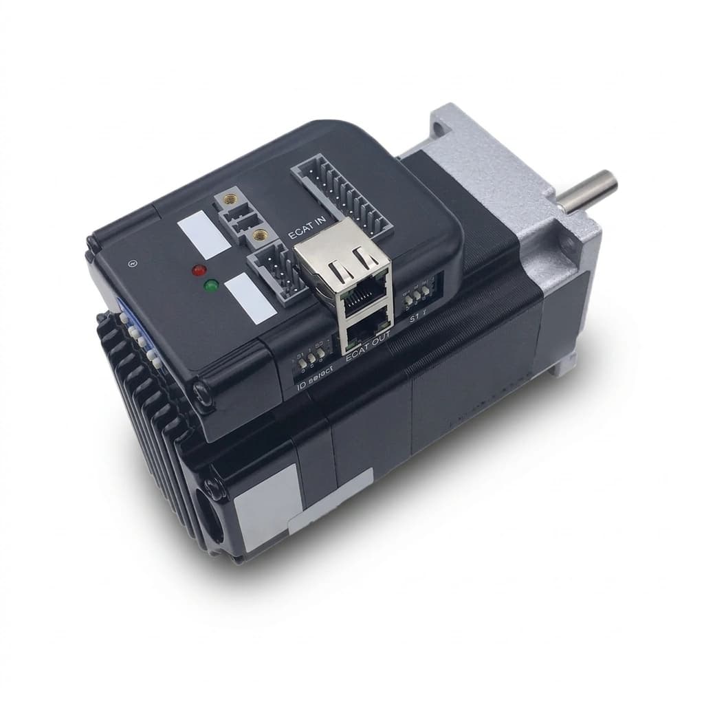
Bus-Controlled Stepper Motors: EtherCAT, CANopen, and Modbus RTU vs. Pulse/Direction Sourcing Guide
Compare bus-controlled stepper motors: EtherCAT, CANopen, Modbus RTU vs. pulse/direction. Check PLC compatibility, wiring costs, and RFQ acceptance criteria.

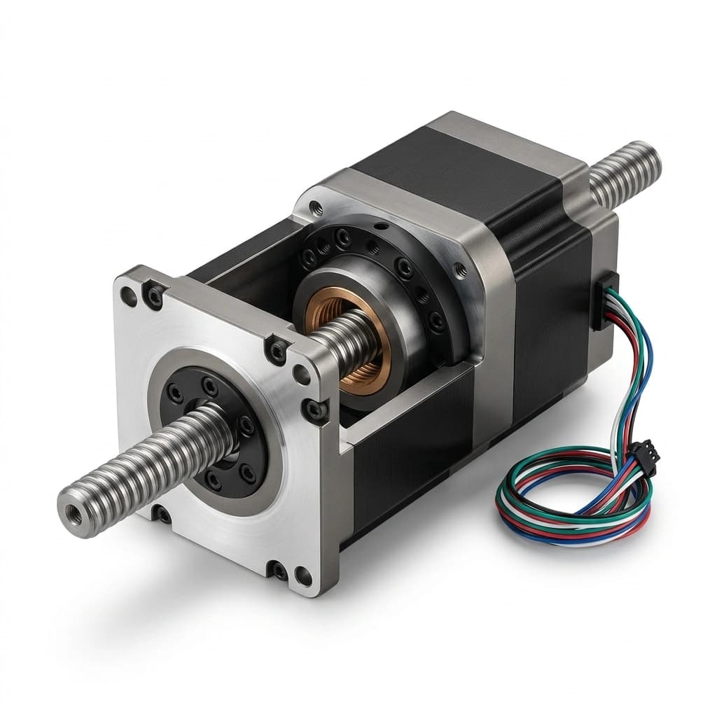
Linear Stepper Actuators: Captive, Non-Captive, and External Lead Screw OEM Sourcing Guide
Compare captive, non-captive, and external linear stepper actuators. Check thrust, screw lead, backlash, and vertical-load risks, then prepare your OEM RFQ.
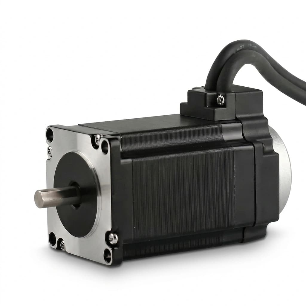
Stepper Motor vs Servo Motor: An OEM Buyer's Decision Framework
When to use stepper motors vs servo motors in industrial machines. Includes cost models, performance comparison data, and a structured decision tree for OEM procurement teams.