
1. Start with running torque
Holding torque is a standstill value. Request available torque at the calculated motor RPM under your actual drive conditions. Evidence & scope
Published 2026-10-31 · Evidence reviewed 2026-10-31 · By NEMA Stepper Motors
Size a 12VDC geared stepper motor for your output speed and load. Here, 12 V means the driver DC bus, not the winding voltage. Calculate motor RPM and torque demand, then identify the measured data needed before choosing hardware.
Calculate motor RPM, required torque and STEP rate.
Ready to screen. Defaults assume 78% efficiency, 1.8° full steps, 1/16 microstepping and 30 arcmin backlash. Edit assumptions above. Changed inputs clear previous results; calculate again.
Holding torque is a standstill value. Request available torque at the calculated motor RPM under your actual drive conditions. Evidence & scope
At the same output RPM, a larger ratio raises motor RPM. Torque multiplication must be weighed against the running torque available at that speed. Evidence & scope
The bus, driver, winding and current conventions must agree. Driver datasheets establish IC limits; the assembled system still needs testing. Evidence & scope
The calculated angle is a command increment. Gearbox play and loaded motor response determine whether the output actually follows it. Evidence & scope
The equations below are steady-state engineering relationships. Defaults are an example, not a catalog motor. Efficiency is a single operating-point input; acceleration, gearbox inertia, resonance and thermal limits need separate checks.
| Output | Formula | Required evidence / limitation |
|---|---|---|
| Motor speed | n_motor = n_output × ratio | Confirm exact ratio and gearbox maximum input speed. |
| Required motor torque | T_load / (ratio × efficiency/100) | Steady load only; add acceleration and friction separately. |
| Pulse rate | n_motor × (360/full-step angle) × microsteps / 60 | Hz at the STEP input; confirm configured external microstep mode. |
| Command increment | full-step angle / (ratio × microsteps) | Nominal angle per command pulse; not accuracy. |
| Screened capacity | min(T_running × ratio × efficiency/100, gearbox limit) | Use a matching running curve. If gearbox limit is absent, capacity is uncapped and provisional. |
| Steady reserve | screened capacity / T_load | 1.5× is an illustrative review trigger, not a qualification standard. |
| Load output power | T_load × 2π × n_output / 60 | Mechanical watts at the load; excludes all losses. |
| Voltage budget | V_bus − I_peak×R_hot − Ke×n_motor/1000 − V_bridge+sense | Optional phase-peak envelope; Ke in V/krpm. Does not model L×di/dt or chopper waveforms. |
| Battery runtime | usable Wh / measured average battery-bus W | Same complete duty cycle, temperature and BMS conditions. |
Mechanical relationships: gearhead reference. Curve requirements: speed–torque reference. The voltage budget is our simplified circuit screen, not a manufacturer torque model. No unmeasured back-EMF or resistance is inferred from holding torque.
| Ratio | Assumed efficiency | Motor RPM | Required steady motor torque | What remains unknown |
|---|---|---|---|---|
| 5:1 | 88% | 175 | 0.5682 N·m | Matched running torque and gearbox rating |
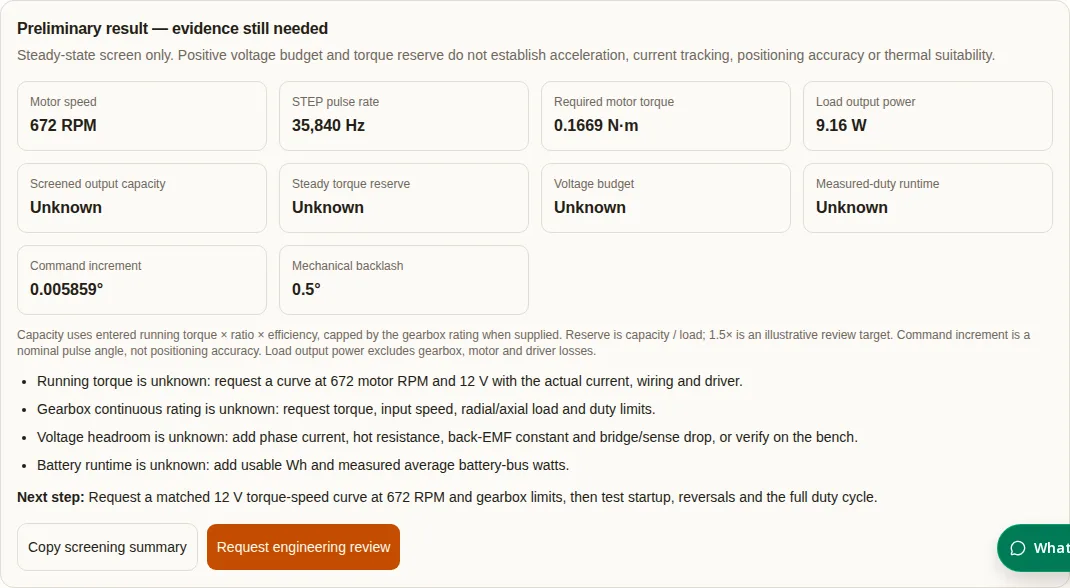
| 19.2:1 | 78% | 672 | 0.1669 N·m | Matched running torque and gearbox rating |
| 40:1 | 65% | 1400 | 0.0962 N·m | Matched running torque and gearbox input-speed limit |
A smaller required motor torque does not prove a better match: the motor must supply it at the higher speed on the actual 12 V drive. The table supplies requirements only, with no predicted torque curve.
| Architecture | Useful when | Request before selection | Tradeoff / alternative |
|---|---|---|---|
| Planetary | Coaxial packaging is important | Continuous / peak torque, efficiency at load, backlash, input speed and bearing limits | Added stages can add loss, play and cost. Compare a lower ratio with a larger motor. |
| Spur | Packaging and cost permit an offset train | Noise, life, lubrication, ratio and output-shaft load rating | Evaluate reversal play and package dimensions against a planetary option. |
| Worm | A right-angle output is useful | Efficiency and tested backdrive behavior under load and vibration | Include heat and power-off holding tests; specify a brake when needed. |
| Direct drive / larger motor | Ratio-induced speed or backlash is unacceptable | Running torque at 12 V, thermal envelope and shaft loads | Larger size/current can be preferable to a high ratio; compare complete system cost. |
These are selection questions, not guaranteed architecture rankings. Manufacturer guidance makes efficiency and permissible torque dependent on the specific reducer and conditions. Neither NEMA frame size nor ratio establishes a gearbox rating.
| Driver | Published operating bus | Current convention / condition | Microstep configuration | Selection check |
|---|---|---|---|---|
| TMC2209 | 4.75–29 V | Up to 2 A RMS / 2.8 A peak; thermally dependent | 8/16/32/64 pin settings; additional modes through UART, interpolation up to 256 | Use the external STEP divisor, not an interpolated internal resolution. |
| DRV8825 | 8.2–45 V | 2.5 A maximum drive at 24 V, 25°C with proper heat sinking | Up to 1/32 | A 1/64 input setting is unsupported. Verify board cooling and current setting. |
| ULN2003 + unipolar geared motor | Separate coil/board analysis required | Not a bipolar current-regulated H-bridge equivalent | Requires a commutation sequencer; no native STEP/DIR indexer | Outside this screen’s drive qualification scope; use exact winding and gear data. |
TMC2209 source · DRV8825 source. The calculator accepts a pulse divisor, not a driver recommendation. Check supported modes, controller pulse timing, RMS/peak conversion, wiring, temperature and supply transients before connecting hardware.
| Parameter | What the tool knows | If unknown, do this |
|---|---|---|
| Minimum bus voltage | Your entered bus value; no battery chemistry is inferred | Measure at the driver during startup and near the pack’s specified cutoff. Use the manufacturer’s BMS limits. |
| Winding I×R | Only from optional phase-peak current and hot resistance | Get resistance tolerance and temperature data. Confirm current mode before converting RMS and peak. |
| Back-EMF | Only from entered phase-peak V/krpm × motor RPM / 1000 | Request the constant and convention. Do not substitute a line-to-line RMS value without conversion. |
| Bridge and sense drop | Only your entered operating-point drop | Use the actual board, current and temperature; fixed per-chip voltage drops are not assumed. |
| Inductive voltage and dynamic torque | Unknown: not modeled | Measure current tracking, loaded torque-speed behavior and startup/acceleration limits. |
| Runtime | Only usable Wh / measured average battery-bus W | Measure full-cycle consumption including holding and electronics, and usable pack energy. |
Example circuit arithmetic: at 12 V, 1.5 A peak, 2 Ω hot resistance, 5 V/krpm phase-peak Ke, 672 RPM and 0.6 V bridge/sense drop, the simplified budget is 12 − 3 − 3.36 − 0.6 = 5.04 V. This is an illustrative input set, not measured hardware and not a running-torque guarantee. There is no universal “12 V cliff” or fixed percentage torque recovery from changing drivers.
For the example 19.2:1 ratio and 1/16 mode, 1.8 / (19.2 × 16) = 0.005859° per pulse. With an assumed 30 arcmin output backlash, reversal play is 0.5°. Specify a measured bidirectional accuracy target; approach from one direction when suitable, or evaluate a lower-backlash gearhead and output feedback.
Microstepping evidence explains resolution versus accuracy. Backlash guidance identifies the effect of output play on reversals. Software compensation does not remove mechanical compliance or validate loaded positioning.
Illustrative calculations, not customer case studies or medical/vehicle suitability claims. No test results or service life are implied.
Inputs: Enter 10 RPM, 5:1, 80% efficiency, 0.4 N·m load, 1.8° and 1/16 mode.
Calculated: 50 motor RPM; 0.1000 N·m required; 2666.67 STEP Hz.
Next: Request running torque at 50 RPM. Test reversal play and settling time under load.
Inputs: Use the defaults: 35 RPM, 19.2:1, 78%, 2.5 N·m, 1.8° and 1/16 mode.
Calculated: 672 motor RPM; 0.1669 N·m required; 35840 STEP Hz.
Next: If entered running torque is 0.2 N·m and gearbox limit is 2 N·m, capacity is capped at 2 N·m: load exceeds rating.
Inputs: Enter 120 usable Wh and a measured 20 W average at the battery bus.
Calculated: 120 / 20 = 6 h for that measured duty and usable energy.
Next: Repeat at the relevant temperature and load. Changed holding time, electronics load or BMS cutoff requires new data.
| Risk | Missing evidence / cost exposure | Minimum next action |
|---|---|---|
| Misuse: holding torque entered as running torque | Overstated capacity and stalled motion | Obtain a matched curve and test with acceleration and load. |
| Scenario mismatch: long holding or high duty | Heating, driver shutdown and unexpected energy use | Log motor/driver temperatures and battery-bus power over the full cycle at worst ambient. |
| Mechanical overload | Gear wear, bearing damage, replacement cost | Check continuous/peak torque, input RPM, shaft forces and overhung distance against gearhead ratings. |
| Power-off load movement | Unverified backdrive / holding behavior | Specify a rated holding device and test loss of power under the real load. |
| Precision overspecification | Paying for microsteps without output accuracy | Set output repeatability and reversal requirements; compare gearhead play and feedback cost. |
| Supply and commissioning cost | Cooling, protection, cables, tuning and qualification time | Quote the complete drive assembly and validation scope; no current price or lead time is claimed here. |
Reviewed 2026-10-31. The sources support the specific principles and device limits indicated below. They do not certify a NEMA Stepper Motors product. No public evidence has been established here for a particular motor’s 12 V torque curve, gearbox life, battery discharge profile or thermal endurance.
Holding versus running torque; curve test conditions. No universal 12 V torque curve is supplied.
Speed, ratio, transmission efficiency, permissible torque and shaft loads. Values remain model dependent.
Supply range, current regulation, 1/32-step indexer and thermal conditions; not a carrier-board continuous-current guarantee.
Voltage range, peak versus RMS current and configured microstep modes. Check the purchased board and configuration.
Command resolution differs from accuracy; incremental torque and load affect small movements.
Output backlash and bidirectional positioning; driver-dependent speed–torque characteristics.
Method and selection questions are editorial engineering synthesis. Numerical examples are calculated from explicitly stated assumptions. Unknown values remain unknown; no ISO/AGMA/DIN/NEMA grade is used to infer backlash, continuous torque or service life.
On this page, 12 VDC is the driver DC bus. A current-regulated bipolar motor may have a much lower I×R winding voltage. Check motor wiring, current and driver supply limits independently.
No. Obtain a torque-speed curve at the calculated motor RPM with the same voltage, current, wiring and driver mode. Holding torque describes an energized stationary motor.
At a fixed output speed it increases motor speed as well as ideal torque multiplication. Recheck running torque, efficiency, gearbox torque and input-speed limits for every ratio.
The input data cannot establish that quantity. The tool still supplies kinematics and required steady motor torque. Request the missing curve, rating or measured power instead of interpreting Unknown as zero.
Holding torque alone does not establish a trustworthy phase-peak back-EMF constant for this screen. Use a manufacturer constant with compatible units or a documented measurement.
No. The optional budget subtracts phase-peak back-EMF, I×R and bridge/sense drop. It omits the time-varying inductive voltage and chopper dynamics. Verify current waveforms and loaded startup on the actual hardware.
It reduces nominal commanded angle. Friction, incremental torque, backlash and compliance can dominate actual movement. Measure repeatability at the output shaft under the real load.
It does not validate that drive. Its pulse model assumes a STEP/DIR controller and the entered full-step angle. Unipolar commutation, actual reduction and winding data require a separate model.
Do not assume a ratio makes it a reliable brake. Obtain backdrive and holding data under the real load, lubricant, wear and vibration conditions. Use a specified brake when power-off load holding is required.
Usable battery Wh divided by measured average battery-bus watts. Include idle, holding, motor, gearbox, electronics and conversion losses in the measured duty cycle. Ah alone does not supply this evidence.
No. Frame size does not establish continuous gear torque, input-speed limit or output bearing capacity. Request the specific gearhead ratings and mounting drawing.
Copy the screening summary, then add exact motor, driver and gearbox part numbers, minimum/maximum bus voltage, current convention, torque-speed curve, acceleration, duty, ambient, shaft loads, accuracy target and quantity.
Use the screening result to copy your inputs and unknowns into an engineering request. Ask for the exact motor/driver curve at minimum bus voltage, gearbox limits and drawings. Include startup, reversal, duty, ambient and output accuracy requirements.
Inquiry Email