
15FBNA1 stepper gear motors datasheet
Calculate command timing, then verify the motor ratings. Manufacturer datasheet unverified. Reviewed .
Request matching manufacturer documentsCheck the command rate
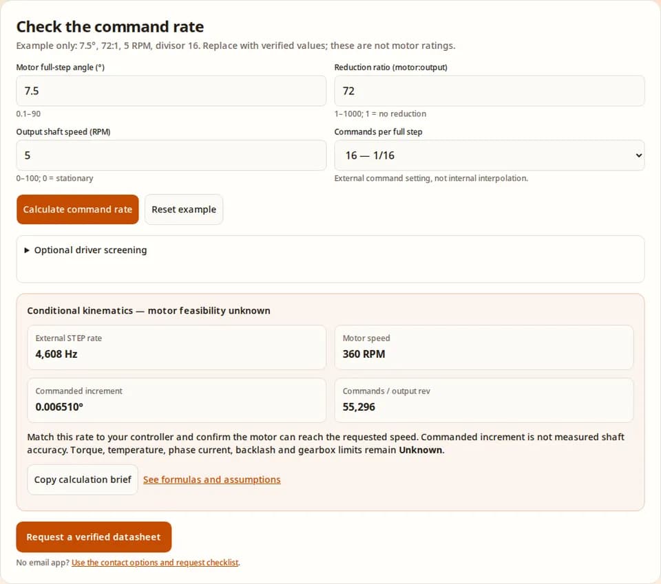
Example only: 7.5°, 72:1, 5 RPM, divisor 16. Replace with verified values; these are not motor ratings.
No current result. Confirm the example inputs, then calculate.
No email app? Use the contact options and request checklist.
What you can decide from this page
Timing can be calculated. With the example 7.5° motor step, 72:1 reduction, divisor 16 and 5 output RPM, the requirement is 4,608 external commands/s. Change either unverified motor assumption before using this for your unit. Reproduce the method.
Mechanical performance remains unknown. No verified running-torque curve, gear rating, backlash or thermal test is available in the reviewed model evidence. A command-rate result cannot certify the load. [S5]
Check the drive separately. An IC bus range does not identify a safe winding voltage or current. A named driver is not proof of motor compatibility. [S1] [S2] [S3]
Resolution is not accuracy. The example 0.006510° increment is commanded resolution; a gearbox can have lost motion larger than that increment. Measure bidirectional positioning. [S4]
15FBNA1 datasheet status: known inputs and missing evidence
As of 2026-10-31, we have not verified an original manufacturer-issued 15FBNA1 datasheet in the primary sources reviewed for this guide. This does not prove that no document exists. The model name alone does not establish manufacturer, body size, winding revision or gearbox construction. The sources below document driver limits and general methods, not model-specific ratings.
| Parameter | Status on this page | Evidence needed before design release |
|---|---|---|
| Motor angle and reduction | 7.5° and 72:1 are illustrative editable assumptions. | Manufacturer drawing/specification tied to the full marking; controlled ratio and step-count verification. |
| Coil resistance, inductance and current | Unknown. No fixed 36 Ω, 14.5 mH or current value is adopted. | Winding diagram, measurement conditions and rated current with its peak/RMS convention. |
| Voltage and terminal assignment | Unknown for the motor. IC bus screening is separate. | Matching winding and connector diagram; lot-specific operating instructions. |
| Torque, gearbox life and temperature | Unknown. No torque curve, endurance threshold or thermal model is assumed. | Matching drive-condition test curves, gearbox load limits and thermal qualification. |
| Dimensions and availability | Unknown. No drop-in interchangeability, stock or price claim. | Approved dimensioned drawing, quote and sample approval. |
A general gear or electrical standard describes a method or requirements. It cannot supply tooth geometry, materials, measured thermal resistance or torque limits for an unidentified motor. An unavailable test report is not treated as measured evidence here.
Calculation method and reproducible limits
Let α be the motor full-step angle in degrees, G the motor-to-output reduction, m the number of external commands per motor full step, and n the output RPM. These are steady command relationships derived from 360° per revolution and 60 seconds per minute. They assume the motor follows every command; acceleration, missed steps and gear clearance are excluded. The step-angle relationship and distinction between resolution and accuracy are described in [S4].
| Quantity | Equation | Example result / interpretation |
|---|---|---|
| Motor full steps/revolution | 360 / α | 48 motor full steps/rev |
| Commands/output revolution | (360 / α) × G × m | 55,296 commands/rev; need not imply measured positioning accuracy. |
| External command frequency | (360 / α) × G × m × n / 60 | 4,608 Hz for an external STEP translator; sequence updates/s for phase-sequenced modes. |
| Commanded output increment | α / (G × m) | 0.006510416…°; displayed to six decimal places. |
| Motor speed | n × G | 360 RPM; verify torque at this motor speed, not at 5 RPM. |
Input ranges are calculator limits, not motor operating ratings: α 0.1–90°, G 1–1,000 and n 0–100 RPM. A divisor must be a listed power of two and match the control mode. Ratio 1 means direct drive. Zero RPM gives zero motion commands, while holding current and heating remain unknown. A non-integer calculated command count is a mathematical average; a finite move still needs a controller rounding strategy and position validation.
Identify windings before selecting a drive
Disconnect all power and isolate the motor from electronics before resistance checks. Label terminals by connector position, photograph the orientation and record a complete pairwise resistance matrix. Do not assign coil polarity or rated current from continuity alone. The following are generic topology checks, not a 15FBNA1 pinout.
| Observed pattern | Possible topology | Next check |
|---|---|---|
| Two isolated resistance pairs | Two separate phase windings may be accessible. | Confirm the matching winding diagram and phase orientation before any drive test. |
| Two isolated groups of three terminals | Each group may contain a center-tapped winding. | Compare the two half-winding measurements and end-to-end path; confirm intended full/half-coil use and current rating. |
| Five leads with shared continuity | A common winding connection may be internal. | Do not attach to a bipolar H-bridge based on appearance. Obtain the actual topology. |
| Unexpected continuity or open circuit | Different topology, embedded electronics, damage or a measurement issue. | Stop. Recheck connector identification and supplier documentation. |
For inductive switching, follow the actual driver datasheet and board schematic. ULN2003A has common-cathode clamp diodes; their COM connection must follow the inductive-load circuit. It is a low-side array, not a bipolar bridge. [S3]
Driver comparison: interface limits are not motor ratings
| Candidate / source | Supply or output constraint | Control in this calculator | Unresolved motor requirement |
|---|---|---|---|
| TMC2209 [S1] | IC operating bus: 4.75–29 V. | External pin mode: 8/16/32/64 commands/full step. Internal interpolation is separate. | Accessible two-phase bipolar winding, suitable low-current regulation, peak/RMS convention and board limits. |
| DRV8833 [S2] | Recommended IC bus: 2.7–10.8 V. A 12 V or 24 V bus is outside this range. | Firmware full/half-step sequence. No STEP translator assumed. | Winding current and sense circuit, topology, thermal design and sequence implementation. |
| ULN2003A [S3] | 50 V is the output ceiling; this is not a motor bus recommendation. | Firmware full/half-step sequence with suitable unipolar windings. | Common/tap topology, winding voltage/current, switching losses and clamp wiring. |
Do not transfer settings between different ICs in a family. A module may add stricter capacitor, regulator or layout limits than the IC. The tool screens only the listed IC range and illustrative control mode; it does not set current or design the power circuit. Selecting a driver resets the divisor so an incompatible microstep mode is not silently retained.
Prepare your datasheet request checklistTorque and speed: the missing decision inputs
Holding torque is a stationary quantity. To decide whether a load can move, obtain a running torque–speed curve for the actual motor, winding connection, bus voltage, phase current, driver and excitation mode. Starting from rest and running after acceleration can have different limits. [S5]
For a proposed output load T and gearbox efficiency η, the idealized steady motor requirement is T / (G × η), before acceleration, friction and service margin. Neither η nor available running torque is verified for this model, so this guide does not turn that relationship into a load approval. The gearbox also needs its own continuous, intermittent and shaft-load ratings.
Minimum alternative when no curve is available: send the required output speed, load torque, acceleration time, duty, ambient and mounting conditions with your motor marking. Request a matching curve or a documented sample test. For a critical production design, compare a current product with published data and qualify it in the same fixture.
Thermal, mechanical and cost risks to resolve
| Risk | Why this tool cannot settle it | Mitigation / alternative |
|---|---|---|
| Overheating or winding damage | Rated current, hot resistance, duty waveform and thermal path are unverified; no case temperature is predicted. | Obtain current and temperature limits; verify the selected winding connection and instrument a controlled test at the intended ambient and mounting condition. |
| Missed steps or lost position | Command timing excludes load transients, resonance, gear clearance and controller limitations. | Use a documented acceleration profile; verify actual position under load and after reversals. Add position feedback if the application requires it. |
| Gear damage or shortened life | Tooth material, lubrication, continuous/peak torque and shaft load ratings are unknown. | Request gearbox ratings and shock-load conditions. Qualify lifetime in the intended duty; consider a documented gearhead alternative. |
| Replacement cost or scenario mismatch | Purchase price alone excludes brackets, connector changes, firmware, test fixtures and downtime. | Compare total integration cost and sample availability. Approve a replacement by drawing and test rather than model-name similarity. |
Intermittent motion is not necessarily intermittent electrical heating: holding current may remain active between moves. Thermal validation must include the full cycle. Fixed temperature limits, percentage deratings and life predictions require the actual material and test evidence.
Mechanical fit and replacement decisions
Record the mounting hole pattern, pilot diameter, body envelope, shaft diameter/flat/length, connector orientation and cable clearance. Measure axial and radial load conditions separately from torque. Do not infer a 15 mm body or a particular shaft size from “15FBNA1”.
A modern geared stepper can be a candidate when its documented speed, torque, backlash and life match the application, but it still may need a bracket, coupling or different controller. A direct-drive motor can remove gear clearance at the cost of different size and torque demands. If bidirectional positioning is critical, compare measured output repeatability or feedback options, not just microstep count. [S4]
For broader ratio selection, see the gear-reduction guide. For system requirements, use the geared-stepper operating-point guide. Electrical assumptions from a 12 V guide are not a rating for this motor.
Three worked timing scenarios
These are reproducible arithmetic examples using assumed 7.5° and 72:1 inputs. They are not customer case studies or measured 15FBNA1 performance.
| Scenario and premise | Calculation / result | Decision and remaining limit |
|---|---|---|
| A — 5 output RPM, generic translator at divisor 16 | 48 × 72 × 16 × 5 / 60 = 4,608 STEP Hz; motor speed 360 RPM. | Check controller timing and a matching 360 RPM torque point. No load capacity is inferred. |
| B — 3.5 output RPM, full-step phase sequence | 48 × 72 × 1 × 3.5 / 60 = 201.6 sequence updates/s; motor speed 252 RPM. | Implement the phase sequence and verify winding/drive suitability. This is not a STEP input rate for ULN2003A or DRV8833. |
| C — stationary command at divisor 16 | 0 output RPM gives 0 commands/s and 0 motor RPM; the commanded increment remains 0.006510416…°. | Holding torque and heating remain unknown. Check the hold-current policy and measure temperature. |
Sources, scope and review date
Maintained by NEMA Stepper Motors. Published · Last reviewed . Recheck within six months, or sooner when a matching manufacturer document or revised driver specification becomes available. Send corrections with the document revision through our contact page.
Primary sources checked on . Their scope is limited to the claims below. None is an original 15FBNA1 motor specification or our own laboratory test report. Driver documents may change; confirm the revision used in your design. Example inputs are assumptions, not findings attributed to these sources.
- [S1] Analog Devices — TMC2209 product documentation
Supports: 4.75–29 V IC bus; external pin settings 8/16/32/64; internal interpolation is separate.
Limit: Driver specifications only; no 15FBNA1 winding rating, current setting or compatibility approval.
- [S2] Texas Instruments — DRV8833 datasheet, Rev. E
Supports: Recommended operating bus 2.7–10.8 V (§6.3); bridge control and current regulation (§7).
Limit: Board and motor constraints still apply. This IC needs phase control, not direct STEP/DIR commands.
- [S3] Texas Instruments — ULN2003A documentation
Supports: Darlington low-side switch array with common-cathode inductive clamp diodes; 50 V output ceiling.
Limit: Not a current-regulated stepper translator. The output ceiling is not a safe motor supply recommendation.
- [S4] Analog Devices — Understanding Microstepping in Motion Control
Supports: Motor step angle and commanded resolution; microstepping does not establish positioning accuracy.
Limit: General motion-control principles; actual geared-shaft backlash and repeatability need measurement.
- [S5] Oriental Motor — Speed–Torque Curves for Stepper Motors
Supports: Running torque depends on speed, drive, voltage, current and winding connection; holding torque is stationary.
Limit: Method reference only. Its example motor curves cannot be substituted for a 15FBNA1 curve.
Evidence needed to replace “Unknown”: an identifiable manufacturer document or a recorded test with unit/lot identity, revision, equipment, drive conditions and uncertainty. Contradictory seller claims or similar-looking units should trigger identity checks, not an average of conflicting ratings.
15FBNA1 datasheet questions
Datasheet and identity
Is this an original manufacturer 15FBNA1 datasheet?
No. This page is a verification guide and conditional calculator. We have not verified a manufacturer-issued, revision-controlled 15FBNA1 datasheet in the reviewed primary sources. Request the document matching the full marking and lot before treating any rating as confirmed.
Can I download a verified 15FBNA1 PDF here?
A verified model-specific PDF is not available here. The linked PDFs document driver ICs only. Send the motor marking, connector photographs and seller document to request a matching specification; the copied calculation brief is not a factory datasheet.
Are 7.5° and 72:1 guaranteed for my unit?
No. They are editable arithmetic assumptions in this tool. Confirm both against the matching documentation or a controlled measurement. A similar part name or appearance does not establish the winding, ratio or mechanical revision.
Does the model name establish its size or manufacturer?
No verified identity or dimension is inferred from the name. Record the complete marking and measure the mounting pattern, body, shaft and connector; request an approved drawing with tolerances.
Calculation and drive
What does the command-rate result mean?
It is the requested number of external STEP edges per second for an assumed translator, or sequence updates per second for the full/half-step examples. It is a timing requirement, not proof that the motor can follow the commands.
Does 1/16 microstepping give 0.006510° shaft accuracy?
No. That is only the commanded increment with the example 7.5° and 72:1 inputs. Gear clearance, load, current control and rotor response affect actual position. See [S4].
Can I apply 12 V or 24 V to a motor described as 6 V?
Do not infer permission from this calculator. A current-regulated driver bus and winding rating are different constraints. Obtain the winding topology and rated phase current, then verify the board and driver documentation. No universal voltage or current recommendation is made here.
Can ULN2003A or DRV8833 accept STEP/DIR pulses directly?
These ICs need phase-sequence control. The calculator limits their illustrative mode to full/half stepping and labels the output as sequence updates. TMC2209 has an external STEP interface; its internal interpolation is not the external command multiplier. See [S1]–[S3].
Qualification and sourcing
How do I identify coil pairs without a pinout?
Disconnect the motor and driver power. Record a resistance matrix between connector terminals and label continuity groups. This can identify possible winding groups, but cannot prove rated current, phase polarity or safe energization. Match it to a verified winding diagram.
Can holding torque predict running torque or gearbox life?
No. Obtain a torque–speed curve for the actual drive conditions and a separate gearbox continuous/peak rating. Shock loads, duty, lubrication and shaft loads need qualification. See [S5].
Does zero RPM mean no heating?
No. It means no motion commands. An energized stationary motor may still dissipate winding heat. Current, hold reduction, ambient and mounting conditions are needed; this tool does not estimate temperature.
Is a NEMA motor a guaranteed replacement?
No. Compare drawing tolerances, shaft, connector, winding, ratio, loaded speed, backlash and controller settings. Budget for brackets, wiring changes, firmware changes and qualification samples. Request an application review rather than assuming a drop-in fit.
Request the matching datasheet or a qualified alternative
Include the full marking and lot, front/rear/connector photographs, measured mounting and shaft dimensions, required output RPM and load torque, duty, ambient, drive board and any existing supplier document. Add the calculation brief above when available. Ask for:
- Manufacturer identity, document revision and matching winding/pinout diagram.
- Rated phase current, peak/RMS convention and applicable winding connection.
- Motor step angle, exact reduction ratio and torque–speed curve under your drive conditions.
- Gearbox continuous/peak load limits, backlash, temperature limits and approved drawing.
- Sample availability and qualification plan before any production substitution.
No verified PDF, price, stock or drop-in equivalent is promised on this page. If you cannot establish the unit’s identity, request a documented replacement candidate and compare it in your fixture.
Compare documented motor product families and the stepper control guide when preparing an alternative design.
Inquiry Email